What motion-control components are used in CT, MRI, DR and SPECT equipment?
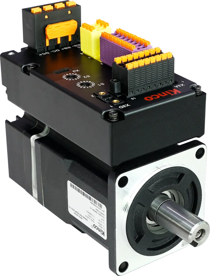
Medical-imaging equipment may use servo drives, motors, feedback and application-specific control for gantry, bed or detector-column axes. The review considers Kinco JD-series drives, SMH motors and compact-drive options against the motion profile, EMC, feedback, failure behavior and regulatory boundary.
Medical imaging equipment OEMs and integrators building MRI, CT, DR, and SPECT systems — gantry rotation, hospital bed positioning, detector column motion, with stringent certification and lifecycle requirements.
Auxiliary-axis candidate · STO and certification scope per exact variant datasheet and equipment-level review
Configuration summary. Candidate motion components cover MRI, CT, DR and SPECT gantry, bed and detector-column axes.
This is a candidate architecture, not a quotation. an engineering BOM review checks each line against your machine, and PLC and HMI programming scopes the control work once the hardware is agreed.
What changes the component choice?
What we check
Selection: Candidate tier review: JD430 with incremental feedback, JD620 with absolute feedback, or JD640 with absolute feedback — subject to equipment-level engineering review.
Selection: A frameless direct-drive route can be evaluated where the documented gantry motion profile and regulatory change plan require it.
Selection: Compact drives (OD124S, FD114) where mechanical envelope is the primary constraint (e.g., column-mounted, in-bed).
Selection: Absolute encoder motors essential when post-power-loss position recovery is required for patient safety scenarios.
Wiring / protocol: Applicable EMC requirements and finished-equipment standards must be confirmed for the target market and installation
Wiring / protocol: Drive enclosure grounding to medical equipotential bonding bar
Wiring / protocol: Shielded encoder cables with strain relief; aerial-plug connectors for movable assemblies
Wiring / protocol: Battery-backup for absolute encoders sized for declared product lifecycle
Migration: Replacing imported European/Japanese motion stacks requires re-validation of dynamic motion profile, EMC immunity, and post-failure behavior per medical device QMS.
Migration: Existing equipment-level FDA / CE-MDR clearances do NOT carry over — substantial change to motion subsystem may trigger re-certification scope. Confirm regulatory pathway before commitment.
Migration: A component-level certificate does not constitute system-level medical device certification — the equipment OEM remains responsible.
Where it may not fit
Class III implantable or life-support equipment requiring extreme safety qualification
Equipment under active FDA 510(k) or CE-MDR clearance review where motion subsystem change would invalidate filing
Cryogenic or hyperbaric medical environments outside standard component rating
Component certificates do not certify the finished machine; the responsible builder or integrator retains system-level validation.
Frequently asked
Does a certified servo component certify the finished medical equipment?
No. A component declaration applies only to the named component and test scope. The equipment manufacturer remains responsible for the finished device's motion risk analysis, EMC, electrical safety, software, quality-system documentation and market-specific regulatory assessment.
What must be reviewed when changing a medical motion subsystem?
Review the motion profile, feedback, braking and failure behavior, EMC and grounding, cable routing, software changes, traceability and the effect on the existing regulatory file. The replacement remains a candidate selection subject to engineering and regulatory review.
How are medical motion-component lifecycle and spare-parts terms confirmed?
Lifecycle, last-time-buy, repair and spare-parts terms must be confirmed in the current supplier quotation or contract for the exact model. A supplier portfolio statement is not a platform-specific supply commitment; commercial scope is confirmed at RFQ.
Application review
Check this architecture against your machine
Send the payload, duty, voltage, protocol, safety scope and any existing part numbers you already know.
Limits. These figures describe the stated configuration, not Automation Liberty customer results. This is a candidate architecture; exact model, compatibility, certification, availability and commercial scope are subject to engineering review and confirmed at RFQ.
Independent engineering and sourcing partner. Product names and trademarks are the property of their respective owners and are used for identification only.
Why no list price? Every quote follows an engineering review of your application — you get a validated price, not a catalog number.
Privacy choices
Analytics is off unless you accept. Necessary site storage saves your choice.Details.